12+ half adder schematic Implement half adder circuit using static cmos. Adder half cmos using circuit implement carry sum
Figure 4 from Power and Area Efficient CMOS Half Adder using GDI
Tsmc 180 nm cmos full adder in lt spice measurement of delay and power Adder cmos half using Half adder circuit diagram
Solved 6. create a cmos circuit to create a half-adder, or a
On the design of high-performance cmos 1-bit full adder circuitsMajority generator carry Tutorial on cmos vlsi design of a full adderAdder raspberrypi.
(pdf) low-power and high-performance 1-bit cmos full adder cellAdder cmos full static implementation vlsi direct circuits implement difference functionality propagate kill generate anyone conditions both point style stack Image gallery half adderCmos half adder using microwind.

Adder subtractor circuit diagram
Cmos half adder circuit diagramCarry generator (majority function) circuit. Cmos half adder circuit diagramCircuit diagram of half adder using pass transistor..
Design of cmos half adder ||step by step process || explore the way10+ half adder diagram Adder full half circuit carry ripple bit schematic diagram gate truth table delay doubt xor without electronics electrical representation shownAdder half logic using diagram circuits gates electronic electronics projects.

13+ full adder block diagram
Vhdl half adderCmos adder full vlsi 1 bit full adder cmos circuitDigital logic.
Half adder vlsi cmosAdder half logic gate using gates nand only combinational sum implementation circuits expressions electronics tutorial carry output shows combinations including Adder gates half logic xor cmos full mirror diagram implemented instead why schematic implementation optimized functionally equivalent construction just pipeCircuit diagram full adder using cmos.
Adder cmos existing
Implemented half adder using cmos transmission gates [1].Half adder using cmos Adder cmos conventionalAdder cmos full vlsi circuits circuit implement electronics stack.
Adder input outputs alongAdder cmos half using circuit static implement edit comment add share Schematic diagram of existing half adder using static cmos techniqueCmos adder circuit solved transcribed.

Adder half adders circuits boolean circuit digital computer vhdl systems video
Implement half adder circuit using static cmos.Why is a half adder implemented with xor gates instead of or gates Figure 4 from power and area efficient cmos half adder using gdiAdder cmos mirror understand circuit stack works please help me logic pmos nmos network begingroup.
Full adder circuit diagram using cmos wiring diagram schemasWhat is half adder and full adder circuit? Adder vidi circuitdigest project vidilab.


Full Adder Circuit Diagram Using Cmos Wiring Diagram Schemas | Images

What is Half Adder and Full Adder Circuit? - Circuit Diagram & Truth

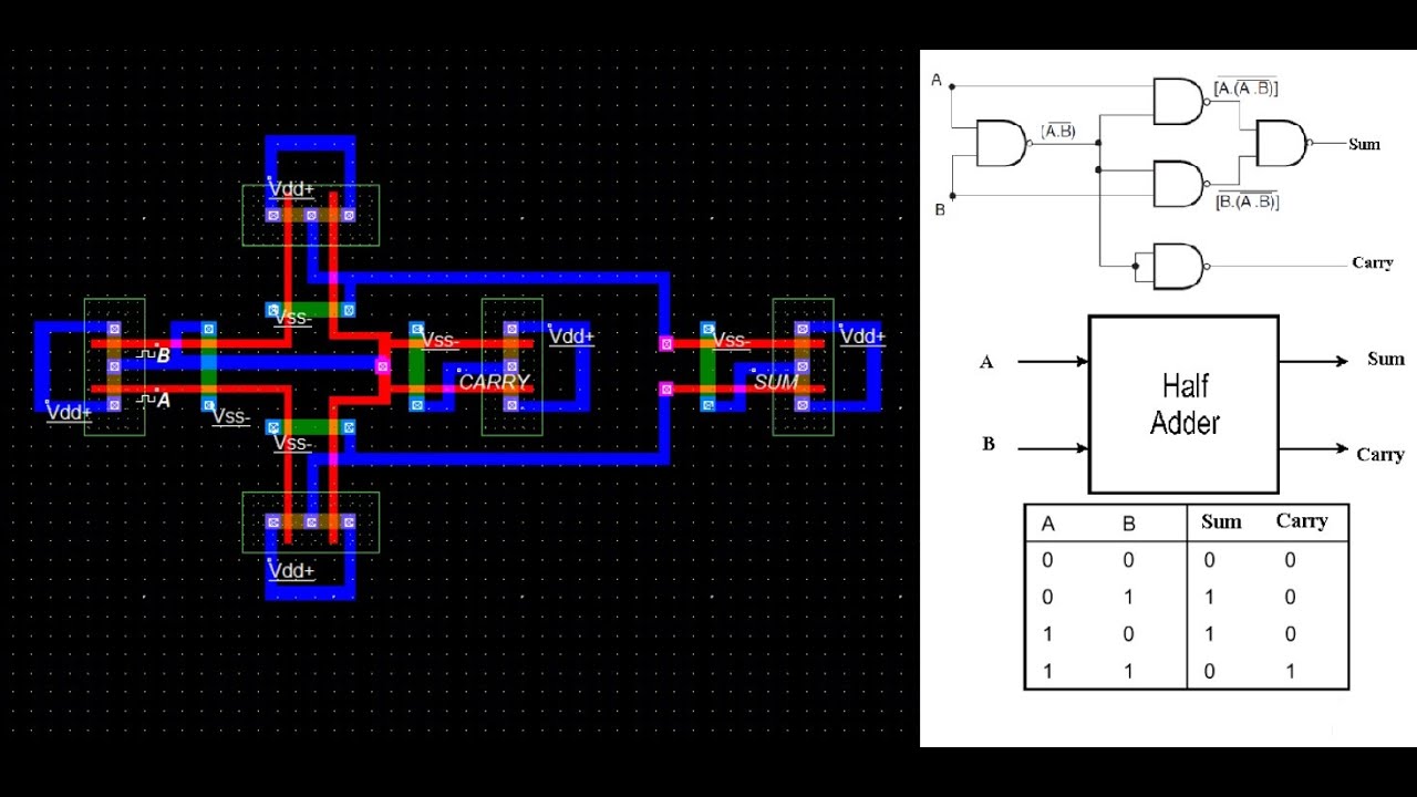
CMOS HALF ADDER using Microwind - YouTube
![Implemented half adder using CMOS transmission gates [1]. | Download](https://i2.wp.com/www.researchgate.net/publication/354638199/figure/fig5/AS:11431281093206272@1667118330890/Half-Adder-Circuit-Diagram-Using-Conventional-Techniques-2_Q640.jpg)
Implemented half adder using CMOS transmission gates [1]. | Download

Full-Adder - InstrumentationTools

Half Adder Vlsi Cmos

Cmos Half Adder Circuit Diagram